Touch and thickness
Metal Card Edge Finishing
The edge is where a metal card is judged in the hand. Edge finishing controls how a 0.3–0.8 mm body feels, reflects light, and survives handling — corners, polish, dark layers, slots, and cut-through details are approved together with the final antenna-safe layout.
Production detail views
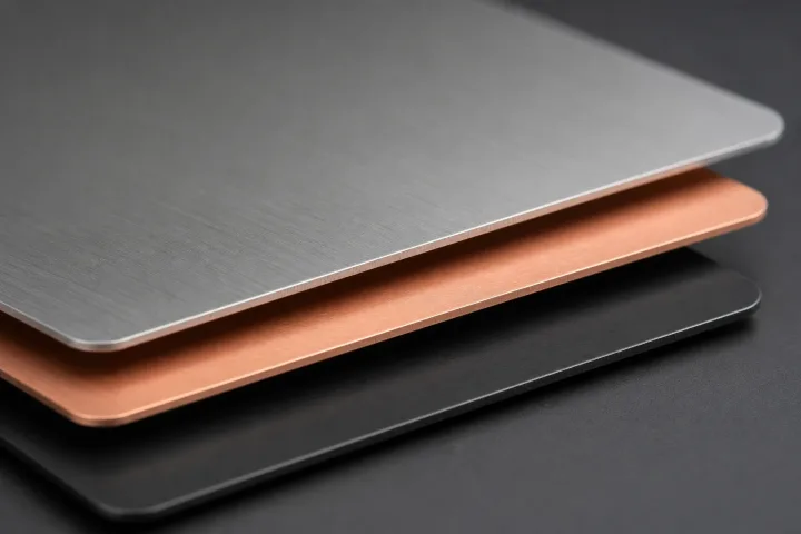
Four edge finishing references for planning the finished metal card.
Three edge profiles side by side, a deburred steel edge, a dark-and-warm pair, and a corner radius — the card in the hand.
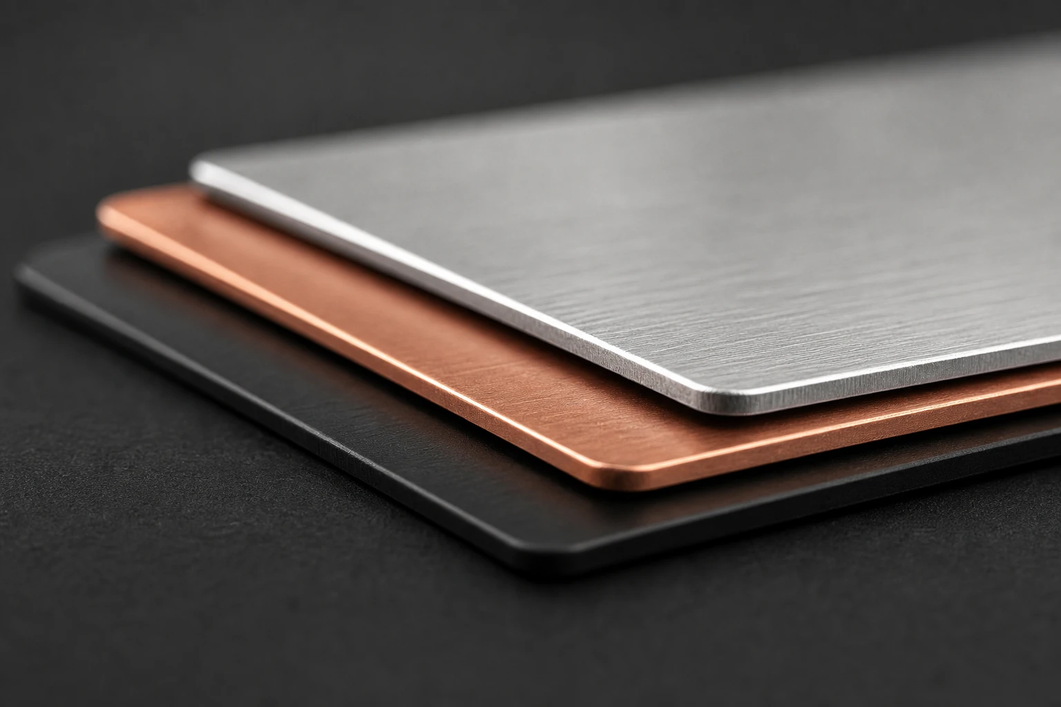
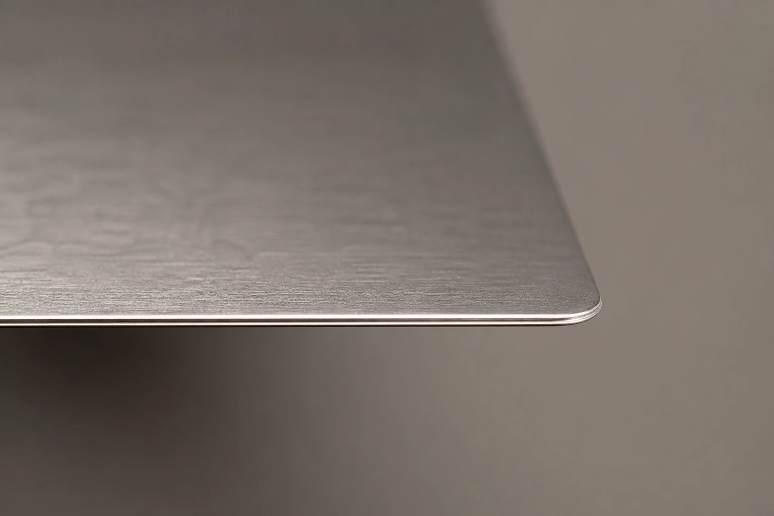
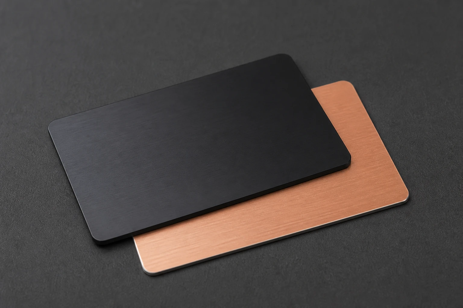
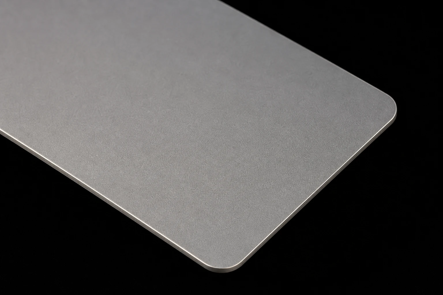
Thickness decides how the edge reads.
Bodies run 0.3 mm to 0.8 mm; edges are deburred and finished, corners follow the CR80 radius unless a custom profile is agreed, and a chamfer or dark edge layer changes both the look and the feel. Slots and holes join the edge conversation early, because every opening passes through the RF construction.
Prove visual and technical performance together.
Approve physical thickness, edge feel, custom cut tolerance, and reader behavior in the final profile.
Best uses
- Corner radius, polished or dark edge detail, custom outlines, slots, holes, and collector-grade handling feel.
- Premium metal card programs where the finish, data zones, and RF construction need coordinated approval
- Projects with a defined artwork file, variable-data need, and reader or scan validation route
Frequently asked questions
How thick is a metal RFID card?
Between 0.3 mm and 0.8 mm depending on construction — enough mass to feel substantial while staying wallet- and reader-practical. The edge treatment decides how that thickness reads in the hand.
What edge treatments are available?
Deburred and finished edges as standard, CR80 corner radius or an agreed custom profile, chamfer control, and a dark edge layer where the build calls for it. Edge feel is approved on the physical sample.
Do slots and custom outlines affect RFID?
Yes — thickness, slots, holes, and custom outlines are RF decisions as much as cosmetic ones. Every cut is reviewed against the antenna route before a die line is released.
Specification
| Format | CR80 85.6 x 54 mm by default; custom outlines after RF review |
|---|---|
| Thickness | 0.3 mm to 0.8 mm depending on construction |
| Minimum order | None — single samples to production runs |
| Production time | About one week after artwork and sample approval |
| RF construction | Antenna, ferrite or hybrid shielding, chip, metal faces, and edge stack specified together |
| Chip routes | NFC tag, standard HF, high-security AES HF, LF compatibility, and selected UHF by reader test |
| Marking options | Laser etch, deep engraving, UV print, white ink, enamel fill, QR, serial, and controlled cut-through |
| Approval flow | Finish sample, encoded working sample, reader check, pre-production approval |
| Primary route | Edge finishing |
| Best use | Corner radius, polished or dark edge detail, custom outlines, slots, holes, and collector-grade handling feel. |
| Approval check | Approve physical thickness, edge feel, custom cut tolerance, and reader behavior in the final profile. |
Related metal RFID card pages
- Laser Engraved Metal RFID Cards
- Deep Engraved Metal RFID Cards
- UV Printed Metal RFID Cards
- White Ink Metal RFID Cards
- Enamel Filled Metal RFID Cards
- QR and Serial Metal RFID Cards
- Metal RFID Card Artwork Specs